chris1967
Been here a while!  Double dip recession, Humous and taramosalata are off the menu!
Posts: 185
|
Post by chris1967 on Nov 28, 2010 11:34:58 GMT
I am planning to modify my Indeed G2 adding a remote control to it and making it into a line preamp in a new case. I would like also to make some modifications that solderdude has proposed. I have bought the MV02-4way motorized remote kit (with motorized alps 100). diyclub.biz/catalog/product_info.php?cPath=1_248_85&products_id=195I am a complete novice to electronics, and apart of the fact that i have (assembled) soldered some very simple kits I have no knowledge at all, but i can follow instructions with ease... The schematic doesn't make much sense, i don't know which input leds to buy and how to connect which ribbon to where...etc... Also how to connect the G2?? Is there a power supply unit to power both units? Any help will be greatly appreciated. |
|
Deleted
Deleted Member
Posts: 0
|
Post by Deleted on Nov 28, 2010 16:16:27 GMT
I am planning to modify my Indeed G2 adding a remote control to it and making it into a line preamp in a new case. I would like also to make some modifications that solderdude has proposed. I have bought the MV02-4way motorized remote kit (with motorized alps 100). diyclub.biz/catalog/product_info.php?cPath=1_248_85&products_id=195I am a complete novice to electronics, and apart of the fact that i have (assembled) soldered some very simple kits I have no knowledge at all, but i can follow instructions with ease... The schematic doesn't make much sense, i don't know which input leds to buy and how to connect which ribbon to where...etc... Also how to connect the G2?? Is there a power supply unit to power both units? Any help will be greatly appreciated. Would need a schematic of MV02 to give suggestions |
|
chris1967
Been here a while!
Double dip recession, Humous and taramosalata are off the menu!
Posts: 185
|
Post by chris1967 on Nov 29, 2010 20:52:32 GMT
Thanks Frans! I will do this shortly...
In the mean time i managed to power it up with a 220 to 9-12 v ac transformer, and managed to connect the ribbons, so that the relays and the motor works fine.
I will post pictures as soon as i can...
|
|
chris1967
Been here a while!
Double dip recession, Humous and taramosalata are off the menu!
Posts: 185
|
Post by chris1967 on Nov 30, 2010 7:00:32 GMT
|
|
chris1967
Been here a while!
Double dip recession, Humous and taramosalata are off the menu!
Posts: 185
|
Post by chris1967 on Nov 30, 2010 7:07:33 GMT
|
|
Deleted
Deleted Member
Posts: 0
|
Post by Deleted on Nov 30, 2010 7:23:17 GMT
Hi Your mess there makes me feel right at home !  Regards Alex |
|
Deleted
Deleted Member
Posts: 0
|
Post by Deleted on Nov 30, 2010 9:11:09 GMT
Connecting the LED's is simple.
You have 5 input LED's
buy standard LED's (2 or 20 mA versions) in the size (1 to 7 mm ?) you want and color you want.
Connect the + of all LED's together (this is the LONG wire of the LED)
Connect these coupled + to pin6 of the indicator connector.
Connect the individual - pins (the short wire) to the corresponding pins 1 - 5.
You can use the G2 power supply of the G2 to power the premote (so no extra trafo needed) but you will have to buy a 12V regulator (7812) + heatsink for it.
Do NOT connect the 24V directly !
Should you like to do that let me know as it will take time to explain.
Now you can switch 4 inputs but 5 is possible need to rewire input 5 in this case.
To connect to G2 you must either set the G2 vol pot at maximum and leave it in there OR remove it and lay 2 straps.
How to if decided what you want.
|
|
chris1967
Been here a while!
Double dip recession, Humous and taramosalata are off the menu!
Posts: 185
|
Post by chris1967 on Nov 30, 2010 20:10:16 GMT
Thank you! In the mean time i had figured the leds out myself...  Is there any problem extending the power transistors (with extension wires) to lets say 5cm per side? (i want to mount them on large heat sinks on either side of the box, that i haven't decided yet how to design it or rather get a dedicated amp chassis)? Is it advisable to twist all connecting wires in order to avoid EMI/RFI ? or will it cause any problems? Can i use solid core wire either copper or silver for all connections (will it have any sonic advantage?)? ( i want ti get rid of the ribbons) I will get back to you on the ps issue... Thanks again, i will be posting questions and photos as i go allong... @sandyk... yea... it is an untidy tidiness...  |
|
Deleted
Deleted Member
Posts: 0
|
Post by Deleted on Nov 30, 2010 21:30:05 GMT
Is there any problem extending the power transistors (with extension wires) to lets say 5cm per side? (i want to mount them on large heat sinks on either side of the box, that i haven't decided yet how to design it or rather get a dedicated amp chassis)? Is it advisable to twist all connecting wires in order to avoid EMI/RFI ? or will it cause any problems? Can i use solid core wire either copper or silver for all connections (will it have any sonic advantage?)? ( i want ti get rid of the ribbons) I will get back to you on the ps issue... Thanks again, i will be posting questions and photos as i go allong... @sandyk... yea... it is an untidy tidiness... upto 10 cm is no problem. the amp is relatively slow and there is no overall feedback that can upset things. You can increase the gate resistors to 470 Ohm to be on the safe side (now 220 Ohm). ONLY twist AC 50/60 Hz carrying wires (to and from transformers) Use screened cables for audio (way better then twisted/braided cables). Use slightly thicker wire for power supply of the G2. Connect the vol pot with screened wire too. Since all wires run absolutely straight from DC to well over 1MHz and no copper cable nor silver cable on this planet can introduce distortion (because there is no un-linear behavior which causes distortion) and no phase shifts, timing problems, lift or drop-off within the 0Hz to 1MHz frequency range e.t.c it may be a waste of time, effort and money to go for expensive cables, in MY opinion. It's just a piece of copper with an insulator around it for Godsake, no magic, as sellers would like you to believe, so you will buy their overly priced junk which is sold with HUGE profits in the name of being better then all the others and create a nice myth around it. Everybody wines about the short pieces of cable between source & preamp and headphone amp & headphone. Yet nobody gives a ... about the quality of copper used in PCB tracks, components, the 100's of solderjoints. Often with badly adjusted solderwave baths creating crappy under-leaded joints to save a buck and sell crap cheap. Connector joints with various types of metal rubbing against each other. Meters of microphone and instrument cables in studios and between equipment in the entire chain the audio has passed through (with a very limited bandwidth), yet that final few cm of cable changes everything... BIGTIME.. go figure. But since this is an audio forum with lots of 'believers' I cannot say this without being taken as a serious hifi enthusiast because they can clearly hear it and seems to reproduce without a doubt. So IF you believe cables will change the sound (by means of 'magic' being sprinkled upon them by sorcerous manufacturers in secret laboratories) THEY will definetily IMPROVE the sound quality big time. The more money you will spend the better it will become, that is something I can quarantee actually. So I say spend your money elsewhere and others say wires are MOST important. You will have to make up your own mind. Sorry, had to do this... was feeling like a rebel again  |
|
Deleted
Deleted Member
Posts: 0
|
Post by Deleted on Nov 30, 2010 22:26:46 GMT
Is there any problem extending the power transistors (with extension wires) to lets say 5cm per side? (i want to mount them on large heat sinks on either side of the box, that i haven't decided yet how to design it or rather get a dedicated amp chassis)? Is it advisable to twist all connecting wires in order to avoid EMI/RFI ? or will it cause any problems? Can i use solid core wire either copper or silver for all connections (will it have any sonic advantage?)? ( i want ti get rid of the ribbons) I will get back to you on the ps issue... Thanks again, i will be posting questions and photos as i go allong... @sandyk... yea... it is an untidy tidiness... upto 10 cm is no problem. the amp is relatively slow and there is no overall feedback that can upset things. You can increase the gate resistors to 470 Ohm to be on the safe side (now 220 Ohm). ONLY twist AC 50/60 Hz carrying wires (to and from transformers) Use screened cables for audio (way better then twisted/braided cables). Use slightly thicker wire for power supply of the G2. Connect the vol pot with screened wire too. Since all wires run absolutely straight from DC to well over 1MHz and no copper cable nor silver cable on this planet can introduce distortion (because there is no un-linear behavior which causes distortion) and no phase shifts, timing problems, lift or drop-off within the 0Hz to 1MHz frequency range e.t.c it may be a waste of time, effort and money to go for expensive cables, in MY opinion. It's just a piece of copper with an insulator around it for Godsake, no magic, as sellers would like you to believe, so you will buy their overly priced junk which is sold with HUGE profits in the name of being better then all the others and create a nice myth around it. Everybody wines about the short pieces of cable between source & preamp and headphone amp & headphone. Yet nobody gives a ... about the quality of copper used in PCB tracks, components, the 100's of solderjoints. Often with badly adjusted solderwave baths creating crappy under-leaded joints to save a buck and sell crap cheap. Connector joints with various types of metal rubbing against each other. Meters of microphone and instrument cables in studios and between equipment in the entire chain the audio has passed through (with a very limited bandwidth), yet that final few cm of cable changes everything... BIGTIME.. go figure. But since this is an audio forum with lots of 'believers' I cannot say this without being taken as a serious hifi enthusiast because they can clearly hear it and seems to reproduce without a doubt. So IF you believe cables will change the sound (by means of 'magic' being sprinkled upon them by sorcerous manufacturers in secret laboratories) THEY will definetily IMPROVE the sound quality big time. The more money you will spend the better it will become, that is something I can quarantee actually. So I say spend your money elsewhere and others say wires are MOST important. You will have to make up your own mind. Sorry, had to do this... was feeling like a rebel again I agree with the vast majority of what Frans is saying here. Frans did say short cables between source and preamp, which I am in agreement with, but longer cables between source and preamp /HA are normally best reserved for cables of a coaxial type construction with a couple of layers of screening, AND most importantly kept well clear of mains leads, or ensure that they cross mains leads at 90 degrees. This is usually best achieved by dropping mains leads from components straight down to the floor, and then keeping interconnects at least several centimetres clear of them. |
|
|
|
Post by victoriaguy on Dec 1, 2010 0:48:21 GMT
So IF you believe cables will change the sound (by means of 'magic' being sprinkled upon them by sorcerous manufacturers in secret laboratories) THEY will definitely IMPROVE the sound quality big time. The more money you will spend the better it will become, that is something I can guarantee actually. So I say spend your money elsewhere ........ Go get 'em, Frans! |
|
chris1967
Been here a while!
Double dip recession, Humous and taramosalata are off the menu!
Posts: 185
|
Post by chris1967 on Dec 1, 2010 17:04:01 GMT
Thanks i must say that i also agree, and i have heard the differences (or no differences) in interconnects and speaker cables. I have no knowledge of electronics though so i had to ask. I am going to use miltary grade coaxial for the internal rca connections, since i have two interconnects i made from some sonar wire that came from a submarine... 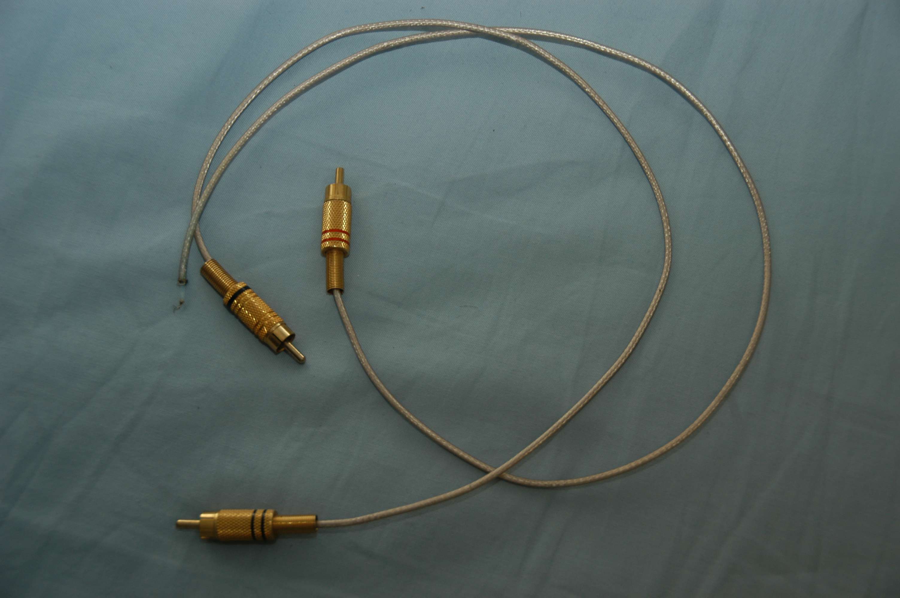 Uploaded with ImageShack.usI have found a project box and i humongous cooler fin (heat sink) and i am going to mount all of the hot stuff of the G2 on it... as i was tapping it though to fit the rca relay pcb i had my first mishap and the spacer broke... 3 point fixture for the pcb then... 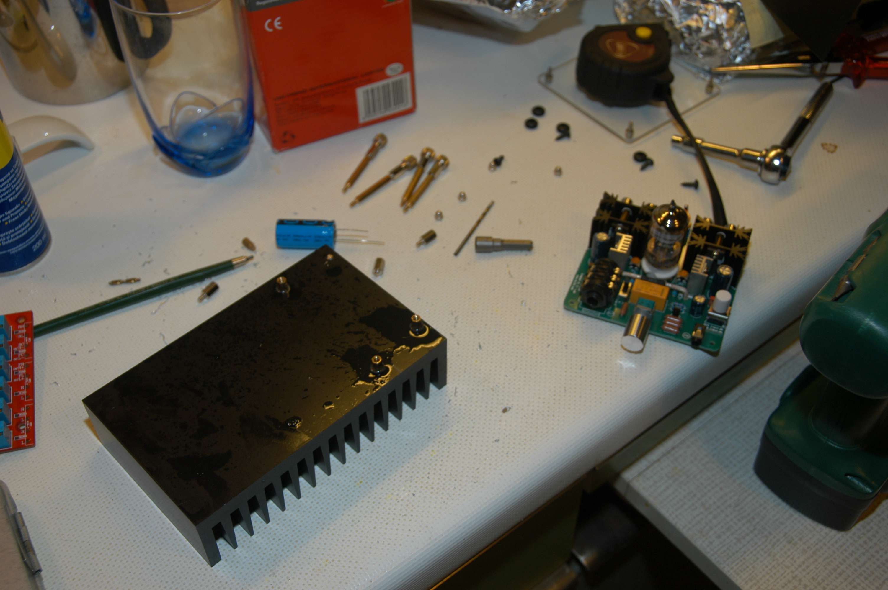 Uploaded with ImageShack.us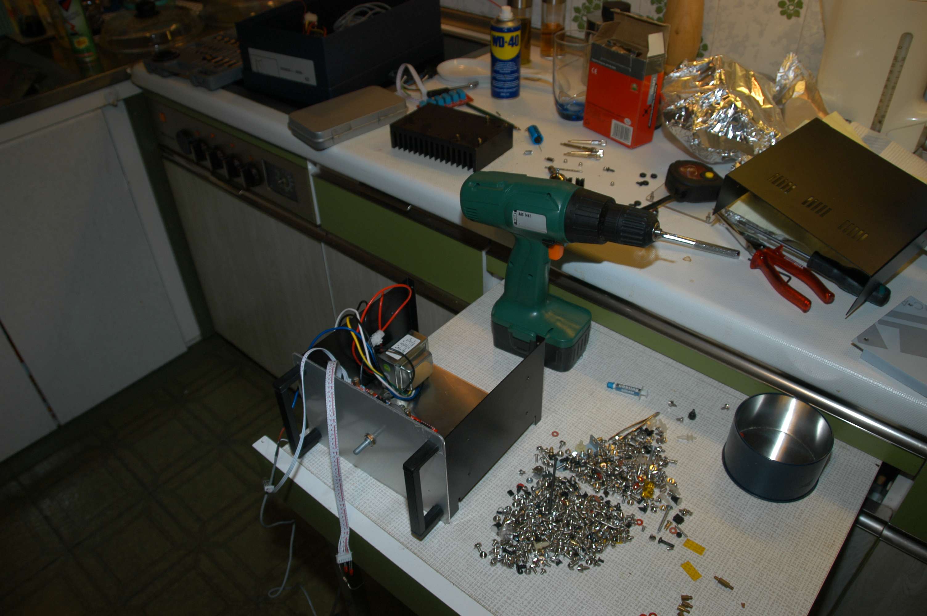 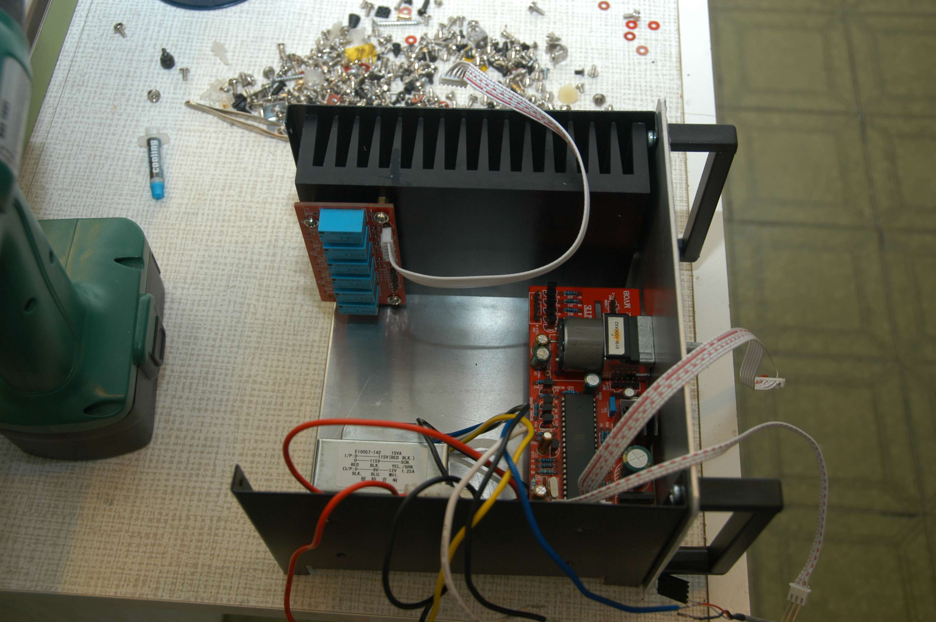 Uploaded with ImageShack.us |
|
Deleted
Deleted Member
Posts: 0
|
Post by Deleted on Dec 1, 2010 18:21:17 GMT
You have more then enough cooling surface.
1st: IF you mount the parts of the G2 on the heatsink they cannot be mounted on there directly or the thing will go up in smoke.
Each MOSFET and LM317 must be mounted properly with INSULATING kits !
2nd: Since you have so much cooling surface you can do the anti-crosstalk mod (TSR2465) but use a linear regulator instead of the TSR2465.
More current will be drawn but the benefits are HUGE.
Even I (who cannot hear differences in interlinks and headphone cables) can CLEARLY hear it and back it up with measurements.
3rd: a transformer near the tube amp isn't a good idea but since the transformer can be deleted too (because of the heatsink).
All that needs to be done is adding a regulator on the cooling fin (yes... isolated) and this can supply the remote control.
The coolingsurface must be mounted tothe outside so air can flow past it.
Inside a box it will get very hot.
|
|
chris1967
Been here a while!
Double dip recession, Humous and taramosalata are off the menu!
Posts: 185
|
Post by chris1967 on Dec 1, 2010 21:54:37 GMT
Thank you Frans!
I am waiting for my gold plated rca sockets and the control knobs.
I read in your pdf about the insulation of the mosfets and the LM317's.
I will get all the case (chassis) mods done, i will do away with the side of the chassis to get the heat sink out, and then i will be needing lots of help to do the power supply and the linear regulator.
This is more than i bargained for... but it is great fun...
More coming up...
|
|
chris1967
Been here a while!
Double dip recession, Humous and taramosalata are off the menu!
Posts: 185
|
Post by chris1967 on Dec 3, 2010 6:59:24 GMT
Since i am going to get the parts today or tomorrow, which linear regulator should i buy, and which isolated regulator?
I am a little puzzled by the fact that the remote works with 12v ac...
|
|
Deleted
Deleted Member
Posts: 0
|
Post by Deleted on Dec 3, 2010 9:10:54 GMT
The remote has a rectifier on board. a 12V AC transformer will give about 17V DC that feeds the remote´s internal 5V regulator. This has to be 'bypassed' and parts can even be deleted from that board.  For supplying the rectifier board a simple (LM)7812 with an insulating kit could be used. The regulator for supplying the glowing current may be an LM317 (WITH insulating kit) Also you will need 4* 10nF ceramic capacitors and 4* 10uF/50V electrlytic capacitors. These regulators all are NOT supplying power in the audiochain so no heroic measures or expensive regulators are needed. |
|
chris1967
Been here a while!
Double dip recession, Humous and taramosalata are off the menu!
Posts: 185
|
Post by chris1967 on Dec 3, 2010 18:07:30 GMT
Wow!! you are really good solderdude!!! Thanks! in the mean time i did a lot of work on the chassis and the final version is in the picture that follows. I cut the box (couldn't do it with the dremel, had to use angle grinder which was difficult to do accurately, but managed all the same), got rid of the handles and put black screws but they will eventually be replaced by black allens. Got another fin to look symmetrical... now the cooling is adequate for at least 50rms class a...  Uploaded with ImageShack.usAnd i bought a lot of components for the G2 mod, more about that later, although i should post the in appropriate thread... at the shop they recommended exactly what you say, and i told them i would ask you first!! is this correct?  Uploaded with ImageShack.us |
|
Deleted
Deleted Member
Posts: 0
|
Post by Deleted on Dec 3, 2010 22:18:43 GMT
yes the schematic is correct (the connections of the 7812)
Since the 24V is already loaded with at least 3300uF there is no need for 100uF at the input.
If I were to build it I would mount 2 ceramic caps as closely as possible to the input-ground pin and one from output to ground pin.
Preferably directly onto the pins.
As electrolytics I would use 10uF/50V on the input and output.
The amp box looks nice and will stay pretty cool.
You could even decide to increase the class A current of the output stage but this can only be done if the heaters are fed with their own power supply.
You might need to get a bigger 24V power supply too as the drawn current will increase with the heater mod and maybe extra if you decide to increase the class-A current.
More then 300mA/channel is not needed.
The total power consumption in this case will be close to 1A@24V = 24W !
|
|
chris1967
Been here a while!
Double dip recession, Humous and taramosalata are off the menu!
Posts: 185
|
Post by chris1967 on Dec 4, 2010 20:20:46 GMT
I cant find words to thank you Frans!
I was thinking exactly the same about the power supply... (to get/build a better one)...
The problem is that this project is getting a little out of hand cost wise, not that i am complaining, just i hope after all these mods that it is a good sounding pre amp...
I will be back shortly...
|
|
Deleted
Deleted Member
Posts: 0
|
Post by Deleted on Dec 4, 2010 20:40:24 GMT
If you are ONLY going to use it as a pre-amp the class-A current can be made very small and you don't need to mount the IRL and MOSFET on the cooling fins but can leave them where they are.
Should you only want to use it as a pre-amp and am not going to use it with a headphone let me know other mods can be done to optimise the G2 for this specific task.
Increasing the class-A current is only needed if you want to drive 16 Ohm headphones too.
The heatsinks are big enough for building a very power full power amp.
You won't need another power supply in this case either.
The heater mod (anti crosstalk) needs to be done though.
|
|
chris1967
Been here a while!
Double dip recession, Humous and taramosalata are off the menu!
Posts: 185
|
Post by chris1967 on Dec 12, 2010 15:01:24 GMT
I see... Ok, I want to use it both as a high quality class A preamp, but also as headphone amp. My plan is to have 3 setups, one for the living room with the main hifi, and i prefer this not to be a diy job (i haven't made up my mind since this is really going to be the most expensive) , the AUNE which i will also modify for use with my pc, and the G2 project in the bedroom connected to sources that have made their way form the main hifi due to upgrades etc... In the mean time i was busy with other tasks (work/revamping the house) so i am not full on the project... I have managed though to start on the G2, and this is how far i am...  Uploaded with ImageShack.usI have ordered some power supplies form the net, as i have also ordered an AUNE and i am going to experiment with them/that also... I don't really like the box though, although the cooling is more than adequate, it looks 90%diy, and 10%factory... i tend to want it the other way around... I am on the lookout for another box, or maybe two to house a good power supply. more as i go along, and i will ask about the G2 in the appropriate thread since i have a question or two... Many thanks. PS. My headphones are the Sennheiser HD 650's which i am very happy with, and i might be looking into the AKG 701's just to hear something different... |
|
chris1967
Been here a while!
Double dip recession, Humous and taramosalata are off the menu!
Posts: 185
|
Post by chris1967 on Jan 22, 2011 10:23:25 GMT
Slowly getting back on the project...
I have not found an appropriate box yet, as the good ones are very expensive... the box that you have seen in the pictures has been destroyed by my clumsiness while drilling holes to it...
In the mean time i have my linear power supplies ( i succeeded in making one for the Aune at 20v, 1,5 amp without blowing up anything...), but i am a little confused about the crosstalk modification.
Can you give me some help as to how do i go about connecting a linear supply (6,5V) on the G2?
Since am going to go linear 25v, 2A (is this right?), should i get a transformer with two secondaries, or can i feed the two supplies directly from the one secondary? and what about bypassing the rectifying circuit on the remote pramp...can all this be done from one transformer or should i get two?
I see that Mike uses a 275V EPCOS Varistor/ 470nf classX2 on the mains... is this a noise filter?, should i be using it on all my power supplies?
Thank you in advance!!
|
|
Deleted
Deleted Member
Posts: 0
|
Post by Deleted on Jan 22, 2011 14:19:39 GMT
You can supply all with 1 linear power supply (24V or 25V doesn't really matter)
For supply-ing the heater you can use:
TSR2465 or other switch mode regulator or (if you have enough cooling surface) you can make a 12V regulator (LM317+resistors or single 7812 regulator which feeds the remote and a LM317 set for 6.3V to feed the heater.
All cooled and mounted using insulator kits.
The 6.3V can also be made with a fixed 7806 + a BAT43 schottky diode or a 7805 + 2 1N4148 diodes.
Then it's all fed with 1 single linear regulated supply but it must be able to do 1A continuous.
a single MOV and cap over the L and N only protects the L and N from surges caused by motors en such.
Normally the MOV will never be activated.
It does little for lightning strikes as you will need something heavier and at least 2 (1 from L to N and one from N to safetyground for it to do something.
Proper filtering requires a more complicated setup or... a mains inlet with a built in filter...
connect the + 12V to the + of C4 on the remote.
Connect the ground (0V) of the 12V supply to the - of C4.
(PD1 is drawn incorrectly in the circuit diagram)
|
|
chris1967
Been here a while!
Double dip recession, Humous and taramosalata are off the menu!
Posts: 185
|
Post by chris1967 on Feb 27, 2011 16:41:13 GMT
Pheweeeeewwwwwww!!! At last managed to complete the project... glad to get my kitchen back...  Uploaded with ImageShack.us Uploaded with ImageShack.usThe bottom of the G2 looks like a battlefield, the circuit got damaged and had to repair using small wires. Needles to say it took many many attempts to fire up, due to dry joints. I had difficulty in following Frans's modifications especially the heater filament supply. In the end i used ready made ones.  Uploaded with ImageShack.usI increased the one power supply heatsink because it was getting very hot,  Uploaded with ImageShack.usI had to insulate the mororised pod, and in the end used wood underneath since it was getting grounding problem with severe noise and hum. Ihad to solder and desolder the wires many times and in the end to make it easier i used simple wire instead of the screened one i started off with... I decided to leave it so because at least it works perfectly now (i left the ribbon maybe change it later).  Uploaded with ImageShack.usThe finished pre amp, i think looking good...  Uploaded with ImageShack.us Uploaded with ImageShack.usI managed to make Hd681's with internal filter and rewire also!!! I would like to thank Frans for all the help and the wonderful mods and designs, and Mike and all the others for the inspiration all these years! Thanks again!!! |
|
chris1967
Been here a while!
Double dip recession, Humous and taramosalata are off the menu!
Posts: 185
|
Post by chris1967 on Feb 27, 2011 18:27:54 GMT
I would also like to thank my friend Frangisko, aka Fabl3d for helping me with some of the soldering work with his steady hand and knowledge...
|
|