|
|
Post by PinkFloyd on Mar 20, 2010 20:56:37 GMT
I thought I'd start a seperate thread "just" for G2 tweaks so if you've got any tips or tricks then please do share them here, thanks. I had a spare couple of hours this afternoon and performed a few minor tweaks.... here they are: 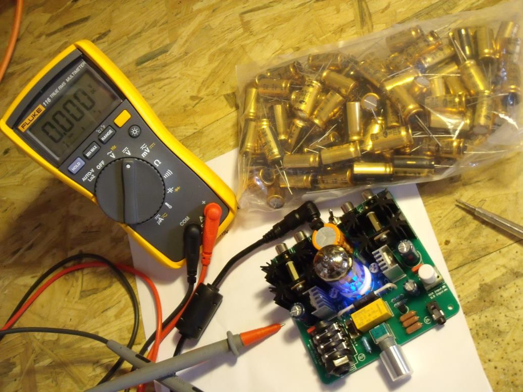 All ready to go First up was the removal of the 25V / 1,000uF coupling caps. I don't like 85C rated caps parked right up next HOT heatsinks.... would much rather see 105C types here: 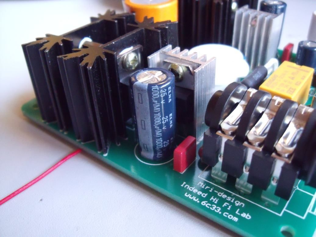 I have gone one better than 105C and fitted 135C rated Samwha VA series in this position.... I have also upped the capacitance from 1000uF per channel to 2200uF per channel. The 2200uF caps I fitted are only 16V rated but this is not a problem as, with the bias set to 13V, they will only ever see 8 volts across them so as long as you keep the bias at 13V then 16V caps are fine in this position. I also replaced the 100nF Wima bypass caps with 3.3uF / 50V types: 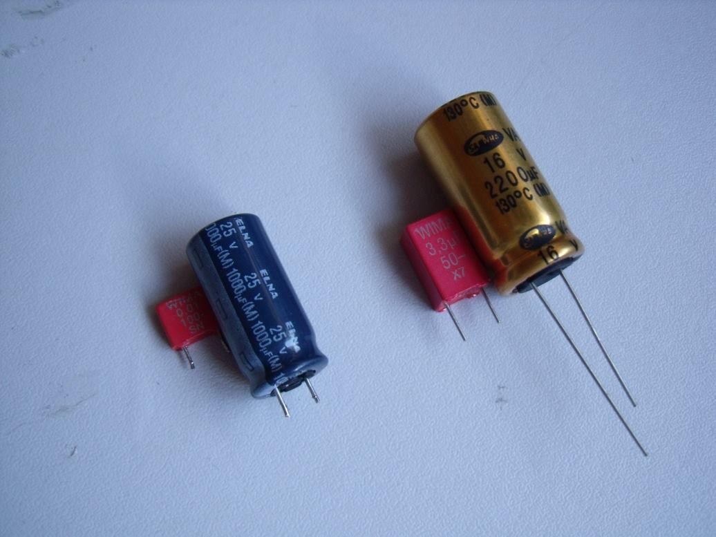 New caps in position: 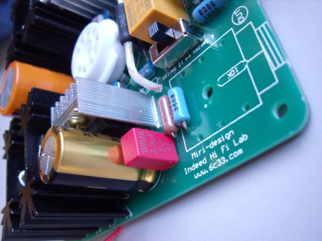 Next up I decided to replace the headphone socket with a high quality gold plated Neutrik type. I also fitted "dummy load" resistors to the head socket so the amp will "always" see a load (I wish all amp designers would fit these).... particularly good with valve amps. 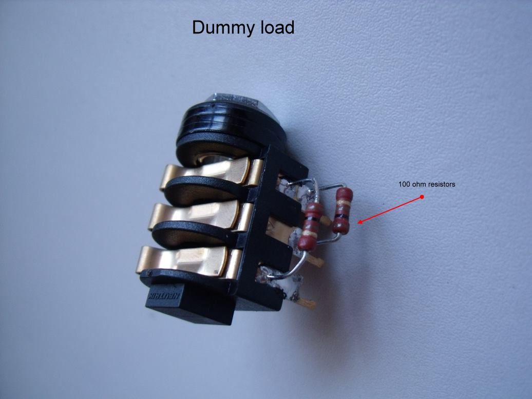 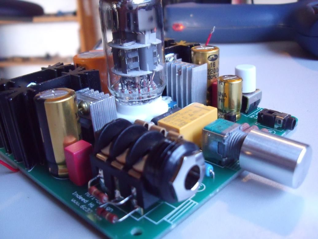 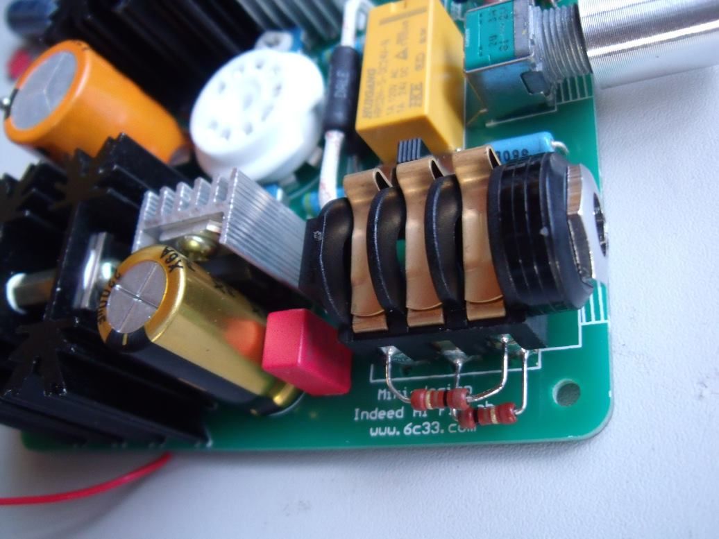 Next up was setting the bias.... my Indeed came with Left channel at 11.6V and right channel at 17V which is pretty crap  I decided to opt for 13V per channel which, IMO, gives the sweetest sound. The measuring points are not as "open" as on the G1 so I decided to fit a couple of PTFE wire "tails" which can have their ends covered (heatshrinked) and be tucked away under the PCB until the next time you want to measure the bias: 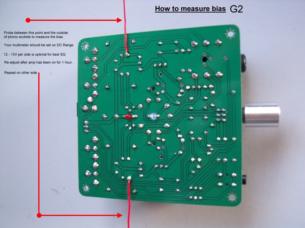 When you're done just cover up the bare "tinned" wires with a bit of heatsleeving: 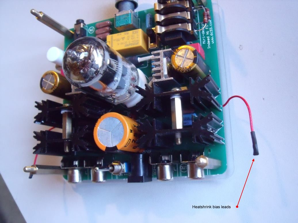 And tuck away until next time: 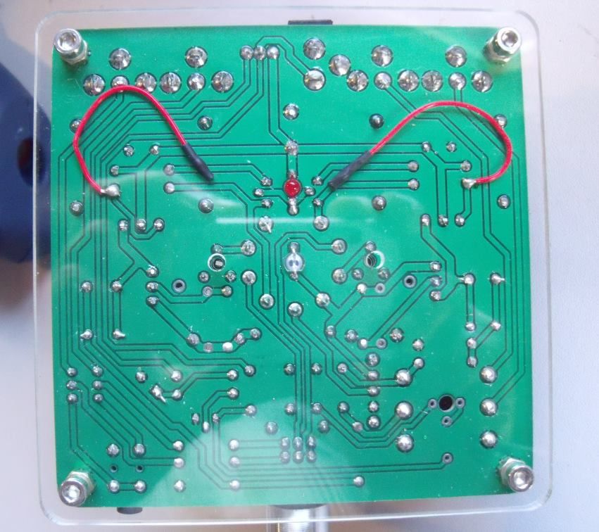 These "tails" make it a LOT easier to adjust the bias.... two multimeters is also the best way to go (with crocodile clip probes) you can set both channels up with ease and don't have to poke about.... just clamp the tails and clamp the other test lead onto the outside of the phono sockets..... all you have to do now is turn the trimpots until both multimeters show 13V...... re-adjust after one hour. Of course, you can do it with just the one multimeter: 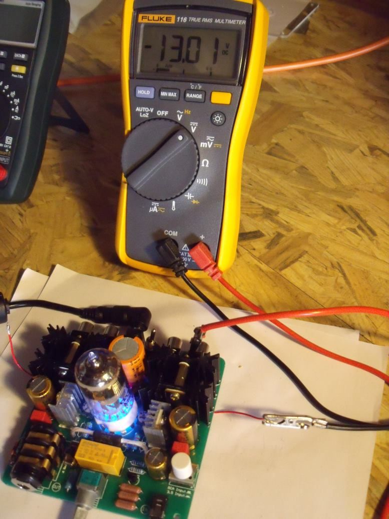 Next up I will be replacing the 25V / 6800uF cap with a 35V / 6800uF type..... both Leo and myself concur that the stock cap is being run at a bit too close to it's max rating and a 35V type would be more suitable here. Right, that's enough for today..... I pass the baton over to you guys.... I hope my initial sprint out of the blocks has been helpful. Mike. 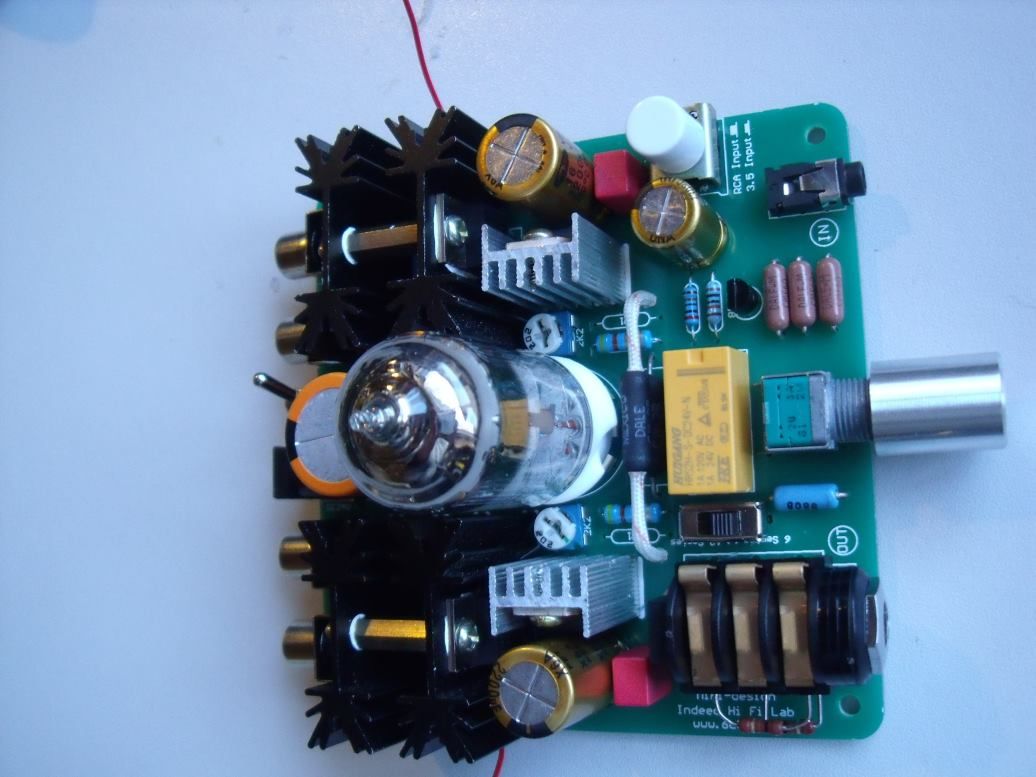 EDIT: Changing the IRF630 MOSFET to IRF510. Highly recommended, much better sound quality and the highs (that are absent with the IRF630 in situ) return big style..... it's easy to do and will only cost a couple of quid: 1: Remove the 1000uF cap. Get a pair of pliers and turn the rod that connects both heatsinks together back and forth a couple of times (this loosens the screw that secures the MOSFET to the heatsink) Remove the screw with a small "flat blade" screwdriver (easier to get in than a philips) 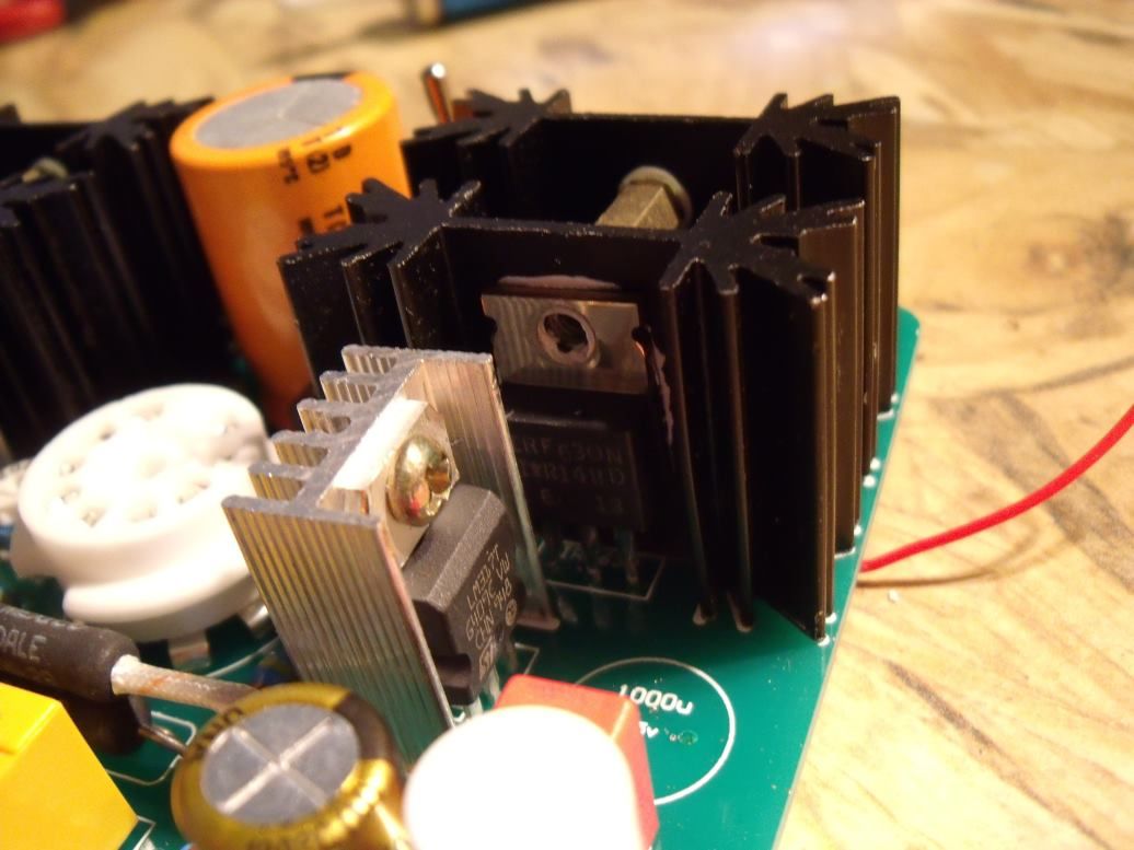 2: Desolder the 630 Mosfet using a desolder pump then remove it: 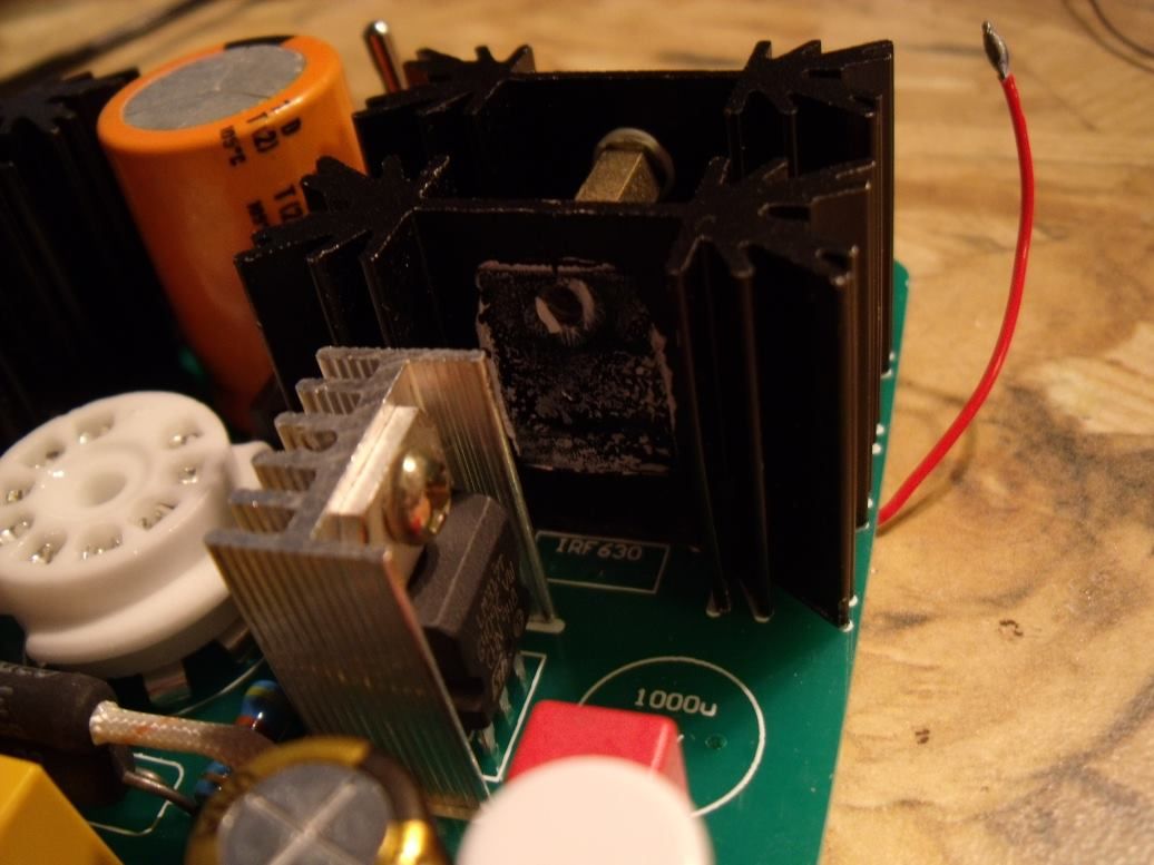 3: Slot in the IRF510, screw it onto the heatsink then solder it (soldering iron temp. high). All you have to do now is replace the 1000uF cap..... repeat for the other side. 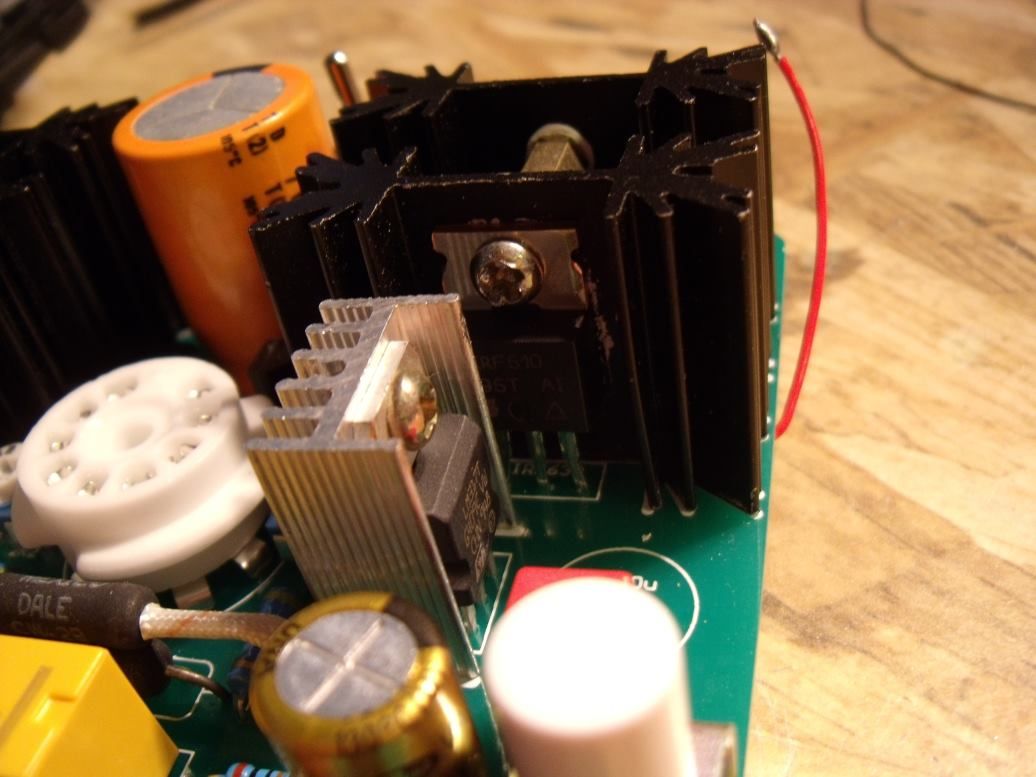 Took me 15 minutes to do both MOSFETS. |
|
|
|
Post by PinkFloyd on Mar 20, 2010 21:43:40 GMT
By the way..... the sound quality since I have matched both channels @ 13V and fitted 2200uF coupling caps has taken a decided LEAP up in performance.... I am hearing details in Yello's "Junior B" that I have never heard before.... a definite improvement for the better.... not as "sweet" sounding, a bit more grain and grit to the proceedings. Leo, I would like to send you a few of these Samwha VA caps, and a couple of the 3.3uF WIMA caps so you can replicate this.... I don't doubt my own ears but it is good to have a second opinion..... I don't know "why" but these Samwha caps have injected some real magic dust into the G2. Don't worry about sending the sample G2 to Attilio, I'd like you to spend time with it, without worrying about sending it on to the next on the list..... I will send Attilio mine..... I really want you to to replicate the above and tell me what you HONESTLY think  Mike. |
|
Deleted
Deleted Member
Posts: 0
|
Post by Deleted on Mar 20, 2010 22:05:32 GMT
I just sit here in AWE!!!! Mike, how you and the other electronically proficient guys on here, know just how to swap and add, and solder, a wire on there, and one over there, and this one might get to hot, to close to voltage limit, i think you get my drift, Fantastic, would love to be able to do that off the top of my head, and then it sounds even better, that`s a great skill.    |
|
Deleted
Deleted Member
Posts: 0
|
Post by Deleted on Mar 20, 2010 22:13:51 GMT
Mick, he's no joker ..... My V2 is AWESOME because of Mike's work.
Mike, how about putting the lights out? It seems that one isn't a problem and the other is part of the circuit design.
Ian
|
|
|
|
Post by PinkFloyd on Mar 20, 2010 22:38:39 GMT
Mick, he's no joker ..... My V2 is AWESOME because of Mike's work. Mike, how about putting the lights out? It seems that one isn't a problem and the other is part of the circuit design. Ian I have no problems with the LEDS Ian, they add eye candy to the pretty "bare bones" skeleton..... if you want to go totally "dark" then its a case of simply snipping one off and replacing the other with a diode..... more details to follow. Mike. |
|
|
|
Post by clausdk on Mar 20, 2010 22:41:13 GMT
The dummyload you talk about, does it just let the amp "think" that a phone it connected ??
Dosen't it add to the ohms of the phones ??
And what good does it do ??
and why is that good ??
trying to learn.. ;D ;D
|
|
|
|
Post by PinkFloyd on Mar 20, 2010 22:50:36 GMT
The dummyload you talk about, does it just let the amp "think" that a phone it connected ?? Dosen't it add to the ohms of the phones ?? And what good does it do ?? and why is that good ?? trying to learn.. ;D ;D The dummy load makes the amp think it has a load (it does!).... as soon as you insert the headphone jack the dummy load "breaks" and goes out of circuit. ie: the insertion of the jack causes the head socket switching to "break"..... it's easier to explain if you look at a headphone socket Claus.... Mike. |
|
|
|
Post by PinkFloyd on Mar 20, 2010 22:54:27 GMT
As soon as you insert the headphone jack the three "prongs" lift.... so the "dummy load" is no longer active.  Reasons why some amps need to see a "load" on switch on? Google it. Mike. |
|
Deleted
Deleted Member
Posts: 0
|
Post by Deleted on Mar 20, 2010 22:55:22 GMT
|
|
|
|
Post by clausdk on Mar 20, 2010 22:55:28 GMT
Ahh the small metal things gets pushed up when a phone is inserted, nice touch..
But why is it good to have a load all the time ? does it make the valves work so it is ready to take action at once ??
Can this be used to burn-in an amp. ??
|
|
|
|
Post by clausdk on Mar 20, 2010 22:56:40 GMT
three posts at once I will do the googleing
|
|
Deleted
Deleted Member
Posts: 0
|
Post by Deleted on Mar 20, 2010 22:57:01 GMT
the valves are NOT loaded by the HP.
only the MOSFET and LM317 is.
|
|
Deleted
Deleted Member
Posts: 0
|
Post by Deleted on Mar 20, 2010 23:00:47 GMT
Too true Ian, know the score regarding your V2 mods, from reading your reply regarding the SQ IMPROVEMENTS, after Mike had done his Magic on it, very talented man.  |
|
|
|
Post by PinkFloyd on Mar 20, 2010 23:01:43 GMT
the valves are NOT loaded by the HP. only the MOSFET and LM317 is. I know! but there is no reason why every head-socket should not be dummy loaded IMO..... It doesn't do any harm to be belt and braces protected  |
|
|
|
Post by clausdk on Mar 20, 2010 23:01:46 GMT
Am I on the right track ??
"The load compensation circuit functions to maintain a nearly constant output impedance"
I guess this gives the amp a more stable enviroment and also less stress on the MOSFETs because they do not have to "power" up and down, when a phone is inserted and removed..
Should the load not match ones favorite headphones ??
To have the best effect..
It is very hard to understand theese things , with my very limited knowledge of electrical parts and what they do..
Can I make the assumtion that it is like a carmotor in neutral and in gear, with the pedal to the metal, the one in neutral will take so many revs that it will die in the longer run..
|
|
|
|
Post by PinkFloyd on Mar 20, 2010 23:12:00 GMT
Am I on the right track ?? "The load compensation circuit functions to maintain a nearly constant output impedance" I'll let Frans explain what a dummy load is, and "why" some amps need to see a load at switch on..... I started this thread, it took me half a day to do the initial "sprint"..... up to you guys to finish the race now  Mike. |
|
|
|
Post by MaN227 on Mar 21, 2010 1:23:09 GMT
very interesting stuff here Mike thanks . EDIT: on lights ... I noticed right away that my red is a subdued red not the laser beam it is the G1. its so dim I don't see any red color projected about like with G1. I don't mind it dimmer I actuallly like it. as I do like the blue one. being that the red gives off not red light glow why is it even there still? bais , since I actually took the time to LOOK at it lol its very easy with my finishing nail looking MM probes. not sure if this is correct or what but it seemed to work perfectly to me. I set amp on its side put the negative probe into the left rca since it stays on its own I just left it alone. making sure to not touch the heatsink. then I simply contacted the above mentioned probe point, using the plexi to give a bit of leverage to hold it steady and insert my smallest Whia phillips head driver and adjusted away. and simply repeated the same using the opposite left rca in, to match the probe side. no wires , no bottom removal. is there damage to be done should the prob contact a different point? say either pin to the left or right of the proper one? if so then i suppose the way it did it should take a steady hand. hope like hell what seemed so easy to do is not completely wrong. please adivse. thanks  mine was way out of whack, 19.6v on right and 14.4 on left. or is that the other way around lol ? damn anywho I adjusted them to 13.3 each as for some reason thy pot that was low to start with would not go any lower than 13.3 I was scratching my head on thatone. the other down to 11 ish. |
|
|
|
Post by attilio on Mar 21, 2010 8:04:12 GMT
Mike don't worry about sending your G2 to me,  it is far more important to us that you and Leo continue with your modding. I intend, like Ian on getting one for myself. Your photos and instructions are fantastic. Even I could confidently tackle these mods with such clear instructions.  And of course when I get my new G2, I will give a review of it. So Peter still gets his feedback attilio |
|
Deleted
Deleted Member
Posts: 0
|
Post by Deleted on Mar 21, 2010 9:59:44 GMT
The small Cap next to the RCA selector Mike, is that a different value, or the same value but better quality?, cant quiet see the labelling on it.
Mick.
|
|
Deleted
Deleted Member
Posts: 0
|
Post by Deleted on Mar 21, 2010 10:10:26 GMT
I'll bite..  Dummy loads are used to load CERTAIN kinds of amps and cables for measuring/testing amps with a 'resistive load or to close off transmissionlines (cables, be it balanced or unbalanced) when no load is connected or measurements have to be made. This can be of great importance in high speed/freq transmissionlines (cables) when more than 1 device is connected to the same source or for HF transmitters that can blow themselves up when the outputs of these amps will be receiving reflected/swung-up voltages back on it's output that exceed their maximum voltage ratings. These dummy loads usually have a resistive character and would be the same ohmage as the normally applied load. For LS amps 4 to 8 Ohms (or higher in case of 100V systems) For HF/data cables this would be the rated impedance (think of 50 Ohms or 75 Ohms for screened wires or whatever the normal load would be in symmtrical transmissionlines) For HP amps there is NO proper load.  HP amps should be able to power HP's ranging from 8 Ohms to 600 Ohms with different inductances. One can argue the output impedance would be leading IF the audiorange would extend above 100 kHz.  most HP will be between 32 and 300 Ohms. What would be the proper dummy for an amp ?  120 Ohms ? 32 Ohms ? 600 Ohms ? 1000 Ohms (is already installed in the standard G1 but for another reason) For testing purposes one would test amps with loads ranging from 8 to 600 Ohms. From a technical point of view 99% of all audio amps I know of do NOT 'need' a dummy load and if they did the designers sure as hell would have implemented them.  Of coarse in the strange world of audioland this is different again and other rules apply. Wether an amp really NEEDS a dummy load is totally dependant of the topology (schematic/design/board layout as you will) of the amp. Now ... the FETS/LM317 in the G1/G2 amps do not turn on and off when a load is connected or disconnected. It's class A so the average power in these parts will always be the same wether they are loaded or not and or having signals or not. Of coarse everybody is entitled to have their own opinions on the use of dummy loads with these amps. Mine is only a technical explanation about dummy loads and it's uses IRL. For 'audio' explanations I am not 'your guy' and a different set of rules will apply. I hope I didn't bore anyone to death with this technical shit and will be glad if even a small percentage of it is understood by the technical noobs. ;D |
|
robertkd
Been here a while!  Electronics Engineer from sunny Queensland
Posts: 111
|
Post by robertkd on Mar 21, 2010 10:33:29 GMT
Nice one Frans  but I'm thinking unless they haven't included a bleed resistor that keeps the output capacitor at DC ground so you don't get pops in your headphone as you plug it in. As for dummy loads isn't that what's between the headphone transducers   |
|
|
|
Post by PinkFloyd on Mar 21, 2010 10:51:33 GMT
Well, Frans..... The WAD HD83 instructions suggest that it is a bad idea to leave the output transformers with an open circuit for extended periods when the amp is on so the 'phones must be connected at all times..... this was my reason for fitting the dummy load (that headsocket is out of the WAD83) The WNA amps ALL had dummy loads fitted.... I will look out the instructions for the "reason".... IIRC it was to prevent the LM6171 from oscillating or some such reason.... So there are two amps I know where a dummy load comes in handy. IMO, they also prevent the occasional pops or crackles when you "hot plug" your headphone jack. Obviously not doing a lot in the G2 but, what the hell.... they were fitted on the head socket so I left them on.... glad I did as we can now discuss "dummy loads" as well as a cornucopia of other stuff  |
|
robertkd
Been here a while!  Electronics Engineer from sunny Queensland
Posts: 111
|
Post by robertkd on Mar 21, 2010 11:00:56 GMT
Mike that's true and for very real reasons being a tube driven transformer output the transformer must all ways have a load on it, doubly so for tube power amps. PS Mike did you tune the bias test points for 3G or GSM phone network?  A suggestion might be to have a 10K resistor soldered to the test point and a wire tail with a ferrite bead or 2 to minimise pickup form GSM phones polling the cell transponder  |
|
Spirit
Been here a while!  That's where I'm gonna go when I die
Posts: 1,107
|
Post by Spirit on Mar 21, 2010 11:06:46 GMT
|
|
|
|
Post by PinkFloyd on Mar 21, 2010 11:14:21 GMT
From Marshall amps (top tips for valves) " Never run a valve amplifier without a load such as a speaker. " www.marshallamps.com/resources/secret_life_of_valves/top_tips.aspAnother random snippet: "Without any load, some beam or pentode amps can oscillate violently, so such amps should always have a load connected unless the designer has made the amps unconditionally stable. " By the way.... you will see the dummy load resistors to the left of the head socket on the WNA MKll board:  and.... you will also see the dummy load fitted to the WNA MK1, directly to the head socket.... 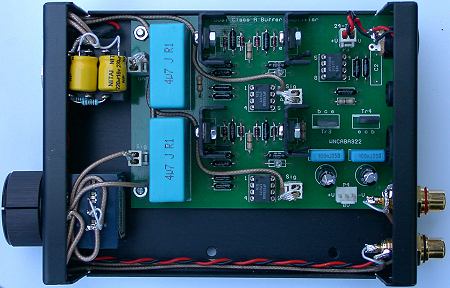 Again... you will see the dummy load resistors next to the head socket on the MKlll: 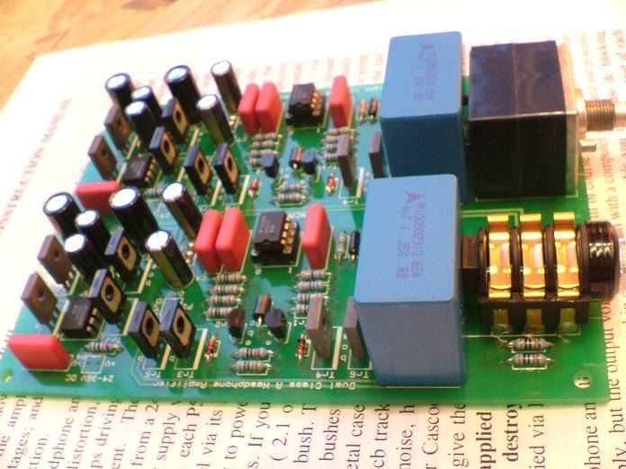 I dunno...... I just got into the habit of fitting them.... they certainly don't do any harm..... belt and braces, belt and braces  |
|


 I decided to opt for 13V per channel which, IMO, gives the sweetest sound.


 I decided to opt for 13V per channel which, IMO, gives the sweetest sound.


 it is far more important to us that you and Leo continue with your modding. I intend, like Ian on getting one for myself. Your photos and instructions are fantastic. Even I could confidently tackle these mods with such clear instructions.


