How to mod your X-Can v3
May 3, 2008 23:02:59 GMT
Post by PinkFloyd on May 3, 2008 23:02:59 GMT
Just thought I'd provide a brief "how to" for any of you guys who want to upgrade your X-Can v3. These are the parts I find give the best sonic results but of course feel free to experiment with other types.... this is really a very basic tutorial on how to get inside the v3 and when inside what to do  Hope it's of use.
Parts:
6 x Panasonic 105C FC 2200uF / 35V capacitors
4 x 1200uF / 35V Panasonic FM
4 x Panasonic 105C FC 100uF capacitors
2 x Capxcon 105C non polar 10uF / 35V capacitors
2 x 1000uF 35V non polar output capacitors
2 x 0.47uF EVOX PME426 polypropylene capacitors
2 metres of high quality solder
7 x UF4007 Ultrafast diodes
For this task you will need a soldering iron (25 watt or greater), a desoldering pump or some desolder braid. You will also need an allen key (hex key) and a philips screwdriver to open the Can up.
Let's start by opening the amp up and removing the board. This is not as daunting as it sounds and is simply a case of firstly unscrewing the back panel (4 hex nuts and a philips screw in the centre of the phono sockets) and lifting it away from the enclosure. There are removal instructions at www.rock-grotto.co.uk/x-can-v2-tube-rolling.htm (these apply to the V3 and the only difference is the V3 has 4 screws instead of 2) just be sure to remember to feed the top screw through the back plate and then through the ground wire connector hole when refitting (pictures at website) OK, you should have managed to remove the back plate by now?
Next you unscrew the four hex keys from the front panel. Once unscrewed pull the front panel toward you and let the entire PCB assembly slide out from the enclosure. That's really the hardest part done! Now remove the valves by lifting them upward out of their sockets (again you can refer to the website for pictorial instructions) it's best to remove them and lay them to one side to keep them safe (makes things easier) You can either perform the cap upgrades with the front panel connected (a good idea to cover it in bubblewrap to prevent it getting scratched) or you can disconnect it from the board if you wish. If disconnecting from the board, here's how you do it:
On the board the white connector next to the screenprinted "LED" marking must be removed. Grasp it, wiggle it and pull upwards... it will pop out easily. Next you remove the connector that sits adjacent to the 4 yellow capacitors, you'll see it has a latch on it (on the side looking toward the 4 yellow caps) get a small screwdriver and slot it into the latch and at the same time grasp the connector, wiggle and pull upwards.... it will pop out easily.
OK, that's all the disconnecting that has to be done on the PCB. Now you move to the board that has the volume control and headphone socket on it. The white connector next to the potentiometer (blue volume control) "SK4" is next to be removed...... again, you will see a latch. slip your small screwdriver into the latch, grasp the connector, wiggle it and pull upwards.. it will pop out. Just one more to be disconnected and that's "SK2" behind the headphone socket.... Grasp it, wiggle it and pull upward. it will pop out easily. Now you should be able to remove the front panel from the PCB. Reconnecting is easy you just pop the connectors back into their slots...... simple eh?
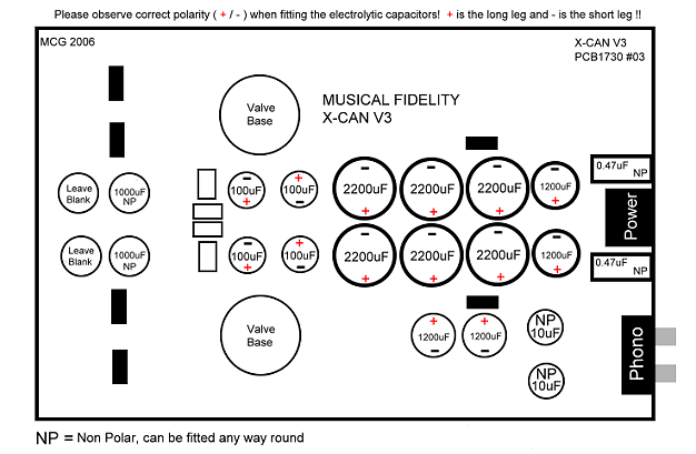
You should now have the PCB in your hand and you're free to walk about with it as it's no longer attached to the rest of the amp. Now fire your soldering iron up and allow it to reach full temperature. Once its hot it's time to remove all of the electrolytic caps (see attached diagram) The best way to do this is to "grab" the cap you're desoldering with one hand whilst applying heat to its pads with the other. Pull them out with a rocking motion as soon as the solder starts to melt on the pad, you'll find they pop out pretty easily once you get the knack of this. The other way to do it which you may easier is to "snip" the excess pins off of the caps to be desoldered, apply heat to each pad until the solder melts and suck it off the board using a desoldering pump.
The caps are glued onto the board so you've got to be pretty "physical" with them. Don't be frightened to pull them hard as they will be going in the bin! A rocking motion to shear the glue bond (between cap and board) is recommended. Don't worry about removing the glue from the board just fit the new caps on top of it.
Once you have removed all of the caps (including the orange 0.47uF ones) you'll now have to mop up the excess solder from the pads in order to expose the hole for the new caps to fit into. This can either be achieved with a desoldering pump or you can mop the excess solder up using desoldering braid and heat applied from your soldering iron. The objective here is to expose all of the holes under the excess solder, don't hold the iron on too long or you run the risk of lifting a pad... if in doubt practice desoldering on an old board (poach one out of a dustbin or nearby skip / dumpster if necessary) or visit www.epemag.wimborne.co.uk/solderfaq.htm which gives some good advice.
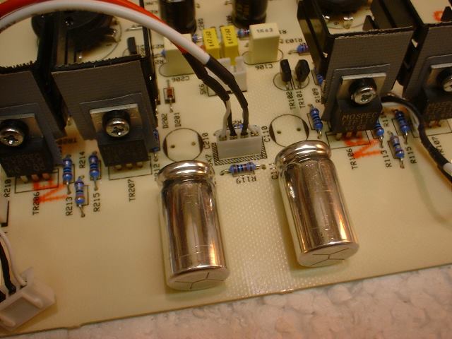
Now it's time to fit those new caps! Have a look at the attached diagrams and you'll see what goes where. You'll also notice a red (+) and a black(-) this shows you what way round the caps go (THIS IS VERY IMPORTANT DO NOT FIT THEM THE OTHER WAY ROUND) The minus (-) side of the capacitor is denoted by a coloured band which runs down the side of it (it also has the shorter leg) and you can tell the positive side (+) by its longer leg. You'll notice there are + signs also printed on the PCB so just remember the longer leg goes toward + and the shorter leg (and band on side of cap) goes to the other side (away from +) Solder all the caps into position (again it may be worth visiting the site mentioned above before doing this) and finish off by cleaning the pad side of the PCB with a toothbrush and some isopropyl alcohol to ensure there are no loose blobs of solder causing a short (there shouldn't be if you've taken care) Ensure you fit the 1000uF non polar caps on their side (laying down on the board) otherwise the front panel PCB may possibly foul them..... only populate the 2 positions (as shown on the diagram) with the 1000uF non polars, leave the other two slots blank.
Fit the 2 x 1000uF non polars like this:

IMPORTANT! NON POLAR CAPACITORS: The 1000uF, 0.47uF and 10uF Non Polar (NP) capacitors can be fitted any way round on the board as polarity is not applicable in these positions.
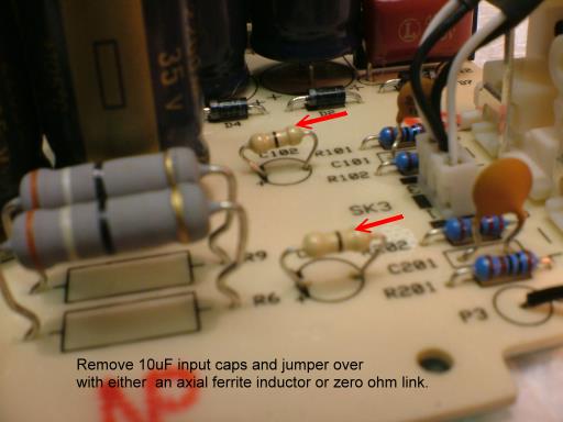
Removal of 10uF input Capacitors (optional) If you are certain there is no DC offset at your source output the 10uF Non polar input capacitors can be safely omitted and the 10uF pads on the PCB can be jumpered over with zero ohm links (supplied in kit) this improves sound quality slightly.
If omitting the 10uF input caps jumper over the pads as shown:

Most modern sources do not have DC on the outputs but it's always best to check with a multimeter, this explains how to check for DC offset but, in this instance, probe between signal and ground at your sources output..... this can be done by attaching interconnects and probing between signal and ground with a CD on "pause" www.rock-grotto.co.uk/dcoffset.htm
Putting the amp back together is simply a reversal of taking it apart and you can refer to www.rock-grotto.co.uk/x-can-v2-tube-rolling.htm again if you're not too sure but I think you'll find it pretty straightforward, you've got this far so slotting the amp back into the enclosure and screwing the front and back plates on again should be easy. Just remember that ground wire that has to be connected between the back plate and the enclosure!
OK, go and turn the amp on and let it warm up for 5 minutes or so before listening. It should be working but, if not, double check all of your solder joints to ensure there are no dry joints. Once satisfied that it's firing on all four cylinders allow a good 100 hours before critical evaluation as the caps require some time to form (burn in) it will sound a lot better than it did "immediately" but give it a few days and you'll be in for a real sonic treat!
Enjoy The Music!

 Hope it's of use.
Parts:
6 x Panasonic 105C FC 2200uF / 35V capacitors
4 x 1200uF / 35V Panasonic FM
4 x Panasonic 105C FC 100uF capacitors
2 x Capxcon 105C non polar 10uF / 35V capacitors
2 x 1000uF 35V non polar output capacitors
2 x 0.47uF EVOX PME426 polypropylene capacitors
2 metres of high quality solder
7 x UF4007 Ultrafast diodes
For this task you will need a soldering iron (25 watt or greater), a desoldering pump or some desolder braid. You will also need an allen key (hex key) and a philips screwdriver to open the Can up.
Let's start by opening the amp up and removing the board. This is not as daunting as it sounds and is simply a case of firstly unscrewing the back panel (4 hex nuts and a philips screw in the centre of the phono sockets) and lifting it away from the enclosure. There are removal instructions at www.rock-grotto.co.uk/x-can-v2-tube-rolling.htm (these apply to the V3 and the only difference is the V3 has 4 screws instead of 2) just be sure to remember to feed the top screw through the back plate and then through the ground wire connector hole when refitting (pictures at website) OK, you should have managed to remove the back plate by now?
Next you unscrew the four hex keys from the front panel. Once unscrewed pull the front panel toward you and let the entire PCB assembly slide out from the enclosure. That's really the hardest part done! Now remove the valves by lifting them upward out of their sockets (again you can refer to the website for pictorial instructions) it's best to remove them and lay them to one side to keep them safe (makes things easier) You can either perform the cap upgrades with the front panel connected (a good idea to cover it in bubblewrap to prevent it getting scratched) or you can disconnect it from the board if you wish. If disconnecting from the board, here's how you do it:
On the board the white connector next to the screenprinted "LED" marking must be removed. Grasp it, wiggle it and pull upwards... it will pop out easily. Next you remove the connector that sits adjacent to the 4 yellow capacitors, you'll see it has a latch on it (on the side looking toward the 4 yellow caps) get a small screwdriver and slot it into the latch and at the same time grasp the connector, wiggle and pull upwards.... it will pop out easily.
OK, that's all the disconnecting that has to be done on the PCB. Now you move to the board that has the volume control and headphone socket on it. The white connector next to the potentiometer (blue volume control) "SK4" is next to be removed...... again, you will see a latch. slip your small screwdriver into the latch, grasp the connector, wiggle it and pull upwards.. it will pop out. Just one more to be disconnected and that's "SK2" behind the headphone socket.... Grasp it, wiggle it and pull upward. it will pop out easily. Now you should be able to remove the front panel from the PCB. Reconnecting is easy you just pop the connectors back into their slots...... simple eh?
You should now have the PCB in your hand and you're free to walk about with it as it's no longer attached to the rest of the amp. Now fire your soldering iron up and allow it to reach full temperature. Once its hot it's time to remove all of the electrolytic caps (see attached diagram) The best way to do this is to "grab" the cap you're desoldering with one hand whilst applying heat to its pads with the other. Pull them out with a rocking motion as soon as the solder starts to melt on the pad, you'll find they pop out pretty easily once you get the knack of this. The other way to do it which you may easier is to "snip" the excess pins off of the caps to be desoldered, apply heat to each pad until the solder melts and suck it off the board using a desoldering pump.
The caps are glued onto the board so you've got to be pretty "physical" with them. Don't be frightened to pull them hard as they will be going in the bin! A rocking motion to shear the glue bond (between cap and board) is recommended. Don't worry about removing the glue from the board just fit the new caps on top of it.
Once you have removed all of the caps (including the orange 0.47uF ones) you'll now have to mop up the excess solder from the pads in order to expose the hole for the new caps to fit into. This can either be achieved with a desoldering pump or you can mop the excess solder up using desoldering braid and heat applied from your soldering iron. The objective here is to expose all of the holes under the excess solder, don't hold the iron on too long or you run the risk of lifting a pad... if in doubt practice desoldering on an old board (poach one out of a dustbin or nearby skip / dumpster if necessary) or visit www.epemag.wimborne.co.uk/solderfaq.htm which gives some good advice.
Now it's time to fit those new caps! Have a look at the attached diagrams and you'll see what goes where. You'll also notice a red (+) and a black(-) this shows you what way round the caps go (THIS IS VERY IMPORTANT DO NOT FIT THEM THE OTHER WAY ROUND) The minus (-) side of the capacitor is denoted by a coloured band which runs down the side of it (it also has the shorter leg) and you can tell the positive side (+) by its longer leg. You'll notice there are + signs also printed on the PCB so just remember the longer leg goes toward + and the shorter leg (and band on side of cap) goes to the other side (away from +) Solder all the caps into position (again it may be worth visiting the site mentioned above before doing this) and finish off by cleaning the pad side of the PCB with a toothbrush and some isopropyl alcohol to ensure there are no loose blobs of solder causing a short (there shouldn't be if you've taken care) Ensure you fit the 1000uF non polar caps on their side (laying down on the board) otherwise the front panel PCB may possibly foul them..... only populate the 2 positions (as shown on the diagram) with the 1000uF non polars, leave the other two slots blank.
Fit the 2 x 1000uF non polars like this:

IMPORTANT! NON POLAR CAPACITORS: The 1000uF, 0.47uF and 10uF Non Polar (NP) capacitors can be fitted any way round on the board as polarity is not applicable in these positions.
Removal of 10uF input Capacitors (optional) If you are certain there is no DC offset at your source output the 10uF Non polar input capacitors can be safely omitted and the 10uF pads on the PCB can be jumpered over with zero ohm links (supplied in kit) this improves sound quality slightly.
If omitting the 10uF input caps jumper over the pads as shown:

Most modern sources do not have DC on the outputs but it's always best to check with a multimeter, this explains how to check for DC offset but, in this instance, probe between signal and ground at your sources output..... this can be done by attaching interconnects and probing between signal and ground with a CD on "pause" www.rock-grotto.co.uk/dcoffset.htm
Putting the amp back together is simply a reversal of taking it apart and you can refer to www.rock-grotto.co.uk/x-can-v2-tube-rolling.htm again if you're not too sure but I think you'll find it pretty straightforward, you've got this far so slotting the amp back into the enclosure and screwing the front and back plates on again should be easy. Just remember that ground wire that has to be connected between the back plate and the enclosure!
OK, go and turn the amp on and let it warm up for 5 minutes or so before listening. It should be working but, if not, double check all of your solder joints to ensure there are no dry joints. Once satisfied that it's firing on all four cylinders allow a good 100 hours before critical evaluation as the caps require some time to form (burn in) it will sound a lot better than it did "immediately" but give it a few days and you'll be in for a real sonic treat!
Enjoy The Music!


